
آزمایشگاه هیدرولیک - civeng دانشکده مهندسي عمران
Hydraulics Laboratory
Introduction
The Hydraulic Laboratory of the Faculty of Engineering at the University of Tehran is one of the oldest hydraulic laboratories in Iran. The building of this laboratory is 75 years old, and some of its equipment has been in use for over 55 years. The laboratory is designed for educational and research purposes in the fields of civil, mechanical, chemical, and mining engineering. Over the years, it has provided faculty members teaching courses in fluid mechanics, hydraulics, and turbomachinery with the opportunity to deliver practical education and conduct research.
The laboratory is also available to serve other universities across the country and to undertake applied industrial projects.
Laboratory Space
The total area of the laboratory, including the entrance and supervision room, is approximately 500 square meters. To conduct experiments, the laboratory is equipped with three tanks as follows:
-
Ground storage tank with a capacity of 90 cubic meters
-
Elevated tank with a constant head of 3.5 meters and a storage capacity of 16 cubic meters
-
Supply source at a water level height of 17 meters above the building
Water from the elevated tank with a constant head of 3.5 meters is supplied from the ground storage tank through two pumps with specific characteristics. Water from the 17-meter-high supply source is also pumped from the ground storage tank.
Water from the elevated tank is distributed to various experimental devices through pipelines with diameters of 200 mm and 300 mm, which run throughout the laboratory. Short-distance connections on the pipes allow easy attachment of any laboratory device. Additionally, locations are provided on the pipes for installing measuring instruments such as pressure gauges and flow meters.
The laboratory is equipped with a wastewater channel network in different sections, which returns water to the ground storage tank after experiments. To drain, replace, or clean the ground tank, a pipe with a valve at a depth of 4 meters transfers water to the municipal sewage system. The presence of these tanks provides excellent facilities for conducting a wide range of experiments.
The laboratory also includes a supervision room of 10.5 square meters, a storage room of 16.6 square meters, and a pump room of 13.2 square meters. A layout plan of the laboratory is provided in the appendix.
Rules and Instructions for Using Laboratory Equipment
Section 1: Entry and Exit
-
Laboratory working hours are from 8:00 AM to 4:00 PM.
-
Entry to the laboratory requires coordination with the laboratory supervisor at least two days in advance.
-
Outside working hours, for safety reasons, students must be accompanied by another person and introduced by a University of Tehran faculty member. The financial and safety responsibility lies with the referring faculty member.
Section 2: Use of Laboratory Equipment
-
All researchers, faculty members, and students must submit a list of the equipment they require to the laboratory supervisor before starting experiments.
-
Responsibility for maintaining the equipment lies with the individual, and the laboratory assumes no responsibility. In case of damage or loss, the individual must repair or replace the item.
-
Any modifications to equipment, such as changing a flume, must be submitted to the laboratory supervisor with the original design and approval from the supervising faculty member before implementation.
-
Users of the equipment must have sufficient experience to prevent harm. The individual and their supervising faculty member are fully responsible for any personal or financial damage resulting from equipment use (e.g., saws or other potentially dangerous tools). The laboratory bears no responsibility.
Section 3: Costs of Using Laboratory Equipment
-
The costs for using each piece of equipment are listed in the table below. (All costs are in Iranian Rial and are based on 2018 rates.)
| نام وسیله | واحد | هزینه برای دانشجوی دانشکده مهندسی عمران (ریال) | هزینه برای پژوهشگران (ریال) |
| فلوم 25 متری موج ساز | روزانه | ||
| فلوم 14 متری | روزانه | ||
| فلوم 8.5 متری | روزانه | ||
| فلوم 5.5 متری | روزانه | ||
| فلوم 4.5 متری | روزانه | ||
| پمپ باد | روزانه | ||
| دستگاه آب مقطرساز | روزانه | ||
| سنگ فرز | روزانه | ||
| دریل | روزانه | ||
| گیره | روزانه | ||
| دستگاه برش چوب | روزانه | ||
| دستگاه جوش | روزانه | ||
| شیکر خاک | ساعت | ||
| شیکر با قابلیت تنظیم سرعت | ساعت | ||
| مجموعه الک | روزانه | ||
| دستگاه سنگ ساب | روزانه | ||
| پمپ 18 اسب | ساعت | ||
| پمپ 6.5 اسب | ساعت | ||
| پمپ 4 پروانه 2 اسب | ساعت | ||
| پمپ کفکش 1 اسب | ساعت | ||
| پمپ کفکش 0.7 اسب | ساعت | ||
| مجموعه آچار | روزانه | ||
| ترازوی دقت گرم | روزانه | ||
| ترازوی صدم دقت گرم | روزانه | ||
| دستگاه اندازه گیری سرعت باد | تست | ||
| Ph متر | تست | ||
| دستگاه هود | تست | ||
| دستگاه فروچاه | تست | ||
| گاری | ساعت | ||
| برق 3 فاز | ساعت | ||
| یخچال | ندارد | ||
| گاز | ندارد | ||
| استفاده از لوله کشی آزمایشگاه و مخزن 18 متری | روز |
Health, Safety, and Environmental Compliance Documents
The following four measures have been identified to enhance laboratory safety, as noted by the respected laboratory supervisor, Dr. Naeini:
Item 1: Due to the transfer of all chemical substances and environmental testing equipment to their respective laboratories, no hazardous chemical experiments are conducted in the Hydraulic and Fluid Mechanics Laboratory. The only remaining device is the laboratory’s distilled water apparatus, which remains in the lab due to its proper function, grounding, and continuous monitoring.
Item 2: The arrangement of experimental devices, both for educational and research purposes, has been organized and is regularly reviewed according to laboratory operations. It should be noted that the layout of the equipment may be improved when conducting new research experiments. This process is supervised by the laboratory supervisor in consultation with faculty members, research assistants, and graduate students. Current evaluations show that the final arrangement works effectively for undergraduate educational experiments and graduate research experiments.
Item 3: The only area in the Hydraulic and Fluid Mechanics Laboratory that uses three-phase electricity is the pump room. Safety measures have been fully implemented in this area: cables are connected from the designated power panel to the pumps in a regular and technical manner, with no issues. Previously, there was a concern when collaboration with the Faculty of Chemical Engineering temporarily required placing a device in the laboratory entrance corridor. This device operated on three-phase power and required temporary wiring for testing. Temporary wiring was not allowed; instead, proper cable installation and three-phase fuses were implemented, which resolved the issue.
Item 4: Regarding the workspace for technical staff and areas for eating and drinking, efforts have been made to ensure they are independent while allowing the laboratory environment to be monitored by the staff.
Finally, the respected faculty authorities and the laboratory safety supervisor are requested to continue periodic inspections of the laboratories. Any safety issues identified should be promptly addressed with the necessary corrective measures.
Educational and Research Equipment
This laboratory is equipped with multiple educational and research devices, which are briefly summarized as follows:
1. Experimental flumes including the Venturi flume, partial flume, and sector gate
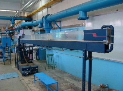
"TQ Inclined Flowmeter for Educational Experiments"
This flume is manufactured by TQEquipment, UK, for teaching channel flow and related installations. The internal dimensions of the flume are 500 × 7.5 × 21 cm, and it comes with a water tank, pump, and side supports for flume installation.
2. Reynolds Number Experimental Apparatus
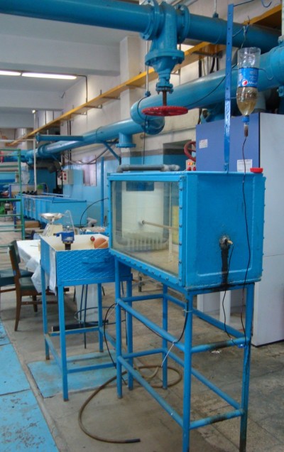
Reynolds Number Tube Flow Experimental Apparatus
This apparatus, manufactured in France, includes a water reservoir from which water is pumped into the Reynolds number test tank. By opening the valve of the pipe inside the tank and allowing a colored fluid to flow through the connected pipe, the experiment is conducted
3. Buoyancy Experimental Apparatus
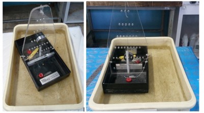
Buoyancy Experimental Apparatus – Front and Rear Views
This device, manufactured in the United Kingdom, includes a float that remains buoyant in water, with a movable weight on it. By adjusting the weight, the center of gravity and buoyancy can be altered to perform the experiment. Additionally, red magnets are placed on the float to maintain its balance.
The specifications of the buoyancy apparatus, according to the manufacturer’s catalog, are provided below:
In addition to the buoyancy apparatus, a scale with the following specifications is also used in this experiment:
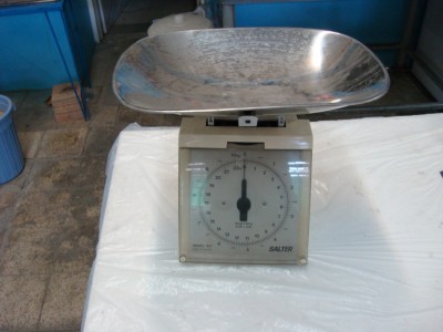
Scale
The above balance is used to measure the weight of the float in the buoyancy experiment. It has an accuracy of 50 grams and a maximum capacity of 10 kilograms.
4- Hydraulic Tables
Two hydraulic tables, manufactured by TQ, are available in the laboratory for educational experiments. A hydraulic table is shown in the figure below. Four experiments—Venturi, flow measurement, water jet, and weir overflow—are conducted on these hydraulic tables. The flow rate in the hydraulic tables available in the laboratory is determined using weights and mass flow calculations.
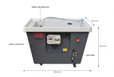
hydraulic bench
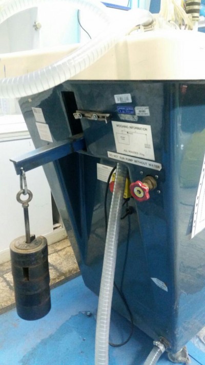
Flow rate determination using weights on the hydraulic bench
5. Venturi experiment
This device, when installed on hydraulic benches, is used to measure the flow rate in pressurized channels. The figure below shows an overall view of the device.
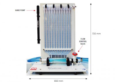
Venturi experiment apparatus
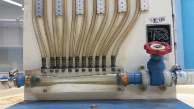
Close-up view of the Venturi experiment apparatus
6. Water jet impact experiment
The figure below shows another hydraulic bench in the laboratory, on which the water jet experiment apparatus—also manufactured by TQ, UK—is installed. This experiment is used to study the momentum principle in fluid mechanics.
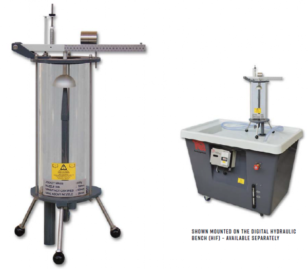
Water jet experiment
7. Blade Tip Overflow Test
This device is used to familiarize with the blade overflow and to determine the flow rate passing through it.
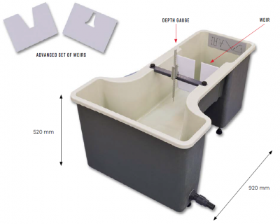
Blade Overflow Test Apparatus
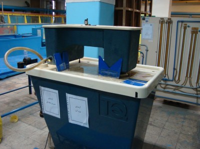
Blade Overflow Test Apparatus
8. Pipe Flow Rate Measurement Test Apparatus
This apparatus is used on a hydraulic bench to familiarize with common methods for measuring flow rate in pipes
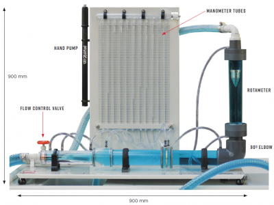
Pipe Flow Rate Measurement Apparatus on a Hydraulic Bench
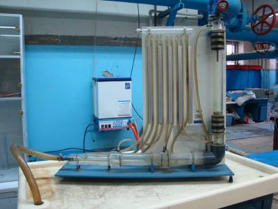
Pipe Flow Rate Measurement Apparatus on Hydraulic Bench
9. Pipe Network Head Loss Measurement Apparatus
This apparatus is used for experiments aimed at observing and calculating pressure loss in pipe fittings, as well as the longitudinal loss in a pipe network.
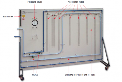
Pipe Network Test Apparatus
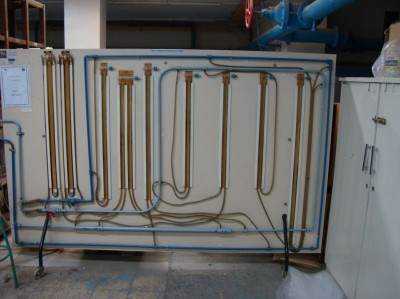
Pipe Network Test Apparatus
10. Center of Pressure Test Apparatus
This apparatus is designed and used to measure the fluid force and the center of pressure on a flat surface.
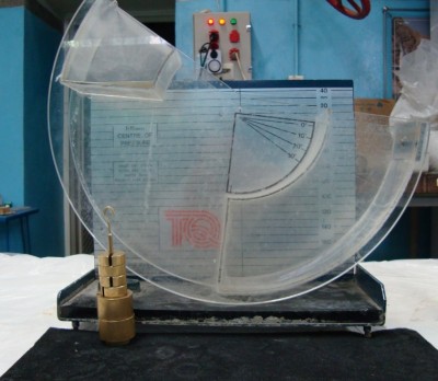
Center of Pressure Measurement Experiment
The figure above illustrates the center of pressure experiment, consisting of the measurement tank, a graduated plate, and 200 g and 50 g weights
11. Viscosity Experiment
This recently added experiment to the laboratory’s educational collection consists of four graduated glass tubes containing cooking oil, motor oil, glycerol, and paraffin, along with four sets of metal spheres with nominal diameters of 2, 2.5, and 3.2 mm, and four guiding funnels
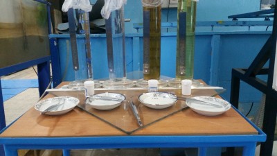
Viscosity Experiment Equipment
12. Cavitation Experiment
This device is used to study cavitation in a Venturi channel and to plot pressure loss curves. The main components include:
-
The main frame and base.
-
A water storage tank, ideally filled 50–75% with water.
-
Tank drain valve.
-
Centrifugal pump.
-
Flow control valve.
-
Flow meter.
-
Venturi chamber.
-
Three pressure gauges (-1 bar to 6 bar).
As illustrated, the setup consists of a transparent rectangular Venturi. The flow is adjusted via the flow control valve. Inlet, outlet, and throat pressures are measured with the pressure gauges, while the flow rate is measured with the installed flow meter.
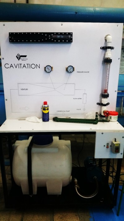
Cavitation Test Apparatus
Research Equipment and Facilities
The laboratory offers research facilities such as four flumes for experimental studies, a hydraulic model simulator, and a wave flume for wave and marine research, accessible to graduate and doctoral students
1. Experimental Flumes
The laboratory is equipped with four flumes of 4 m, 6 m, 10 m, and 14 m lengths, as well as a water level measurement device. These flumes allow for modeling of flow, sediment transport, and hydrodynamic studies. The figures below show the different types of flumes available in the laboratory.
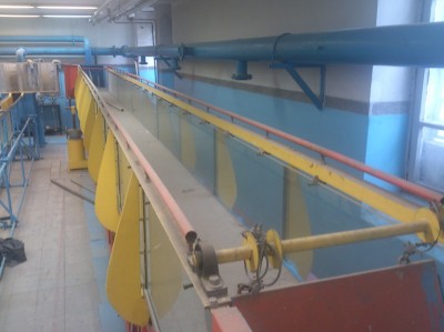
"14 m Laboratory Flume"
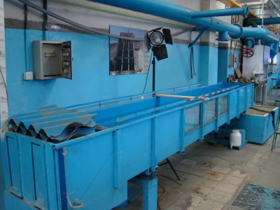
The 4-meter flume is used for research purposes and has dimensions of 4.5 × 0.6 × 0.3 m. Flow is supplied from the tank to the flume by a submersible pump. A track is installed along both sides at the top of the flume to allow movement of measurement instruments
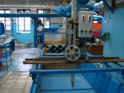
Water Level Measurement Device, moving along rails in both longitudinal and transverse directions of the flume.
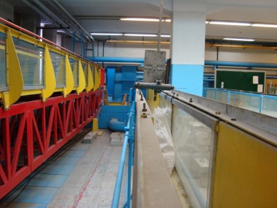
"View Inside the 10-Meter Flume"
This flume features a water level measurement device that runs on side rails. It measures 10 × 0.4 × 0.2 m. The walls are primarily iron, with a glass section to enable observation and recording of the experiments.
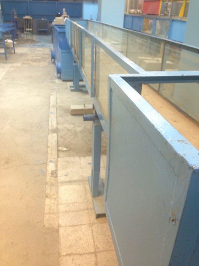
"6-Meter Flow Flume"
2. Hydrology Model Apparatus
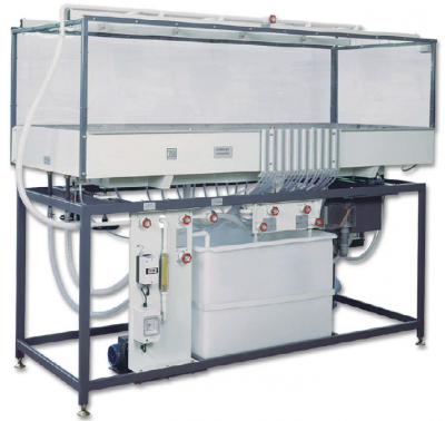
This device, manufactured by TQ, UK, is capable of modeling rainfall-runoff processes as well as conducting studies on flood control and water flow networks in soil. The figure below shows an overall view of the apparatus.
3. Wave-Generating Flume
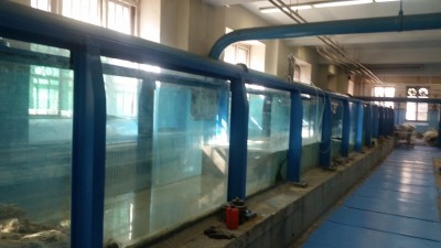
Wave Flume
The wave flume is one of the essential and important facilities in coastal and hydraulic engineering laboratories, required for any major hydraulic and marine research center. In fluid dynamics, a wave flume (or wave channel) is a laboratory device used for physical modeling of water waves to study their characteristics and effects on coastal structures, offshore structures, sediment transport, and other related phenomena.
A wave flume is a special type of wave basin in which the channel width is much smaller than its length. This makes the generated waves approximately two-dimensional (2DV) in the vertical plane. Consequently, the velocity component perpendicular to the channel walls is much smaller than the other two components of the three-dimensional velocity vector. This feature makes the wave flume suitable for studying two-dimensional vertical (2DV) structures, such as cross-sections of breakwaters. Three-dimensional structures with small blockage ratios (ratio of structure width to channel width) can also be tested in the wave flume, for example, calculating wave forces on a vertical cylinder with a diameter much smaller than the channel width.
Waves are usually generated mechanically, although wind-wave flumes capable of creating waves via airflow over water are also available. The wave generator typically consists of a rigid plate that moves rotationally or translationally. Advanced wave generators are computer-controlled and can produce regular waves, random waves, solitary waves, wave groups, and even tsunami-like waves. The wave generator is placed at one end of the channel, while the studied structure (or a wave absorber) is positioned at the other end. (Currently, the laboratory is equipped with such facilities.)
Side walls are usually equipped with windows or made entirely of glass to allow clear observation and facilitate the use of optical instruments, such as Laser Doppler Velocimeters or PIV systems. (The wave flume in the laboratory has glass walls on both sides, allowing full visibility.)
Laboratory wave measurement equipment can be classified into four categories:
-
Wave Basin: A nearly square basin for three-dimensional wave studies.
-
Wave-Stretch Channel: Allows two-dimensional wave studies; a top-mounted towing system can move laboratory models along the channel. (Designs for this equipment have been prepared and can be implemented when funding is available.)
-
Wind-Wave-Current Channel (Coastal Flume): Used to simulate shallow to intermediate depth waves, optimize wave generation parameters near the coast, study coastal processes like wave energy dissipation, sediment transport, and infrastructure design.
-
Wind-Wave-Current Channel (Dual-End Basin): Wave generators are placed at both ends, enabling the study of wave energy dissipation and simultaneous wind and flow effects. Special turbines generate wind over the water surface in the closed channel. This flume can be used for studies of extreme ocean waves, wave-current interaction, and wind-wave interaction (implementation is possible depending on funding).
The current wave channel in the Hydraulic and Fluid Laboratory of the Civil Engineering Faculty at the University of Tehran corresponds to the second type in the above classification. Provisions for the towing section have been considered and may be installed in the future. The flume is built on a concrete foundation measuring 26 m in length, 1.8 m in width, and 0.5 m in thickness. The channel itself is 25.2 m long and 1 m wide.
The channel walls are designed with 2 cm laminated glass for a height of 1.3 m, allowing water to flow up to 1 m with an additional 15 cm crest and 15 cm freeboard.
The initial 1.8 m section of the channel is designed for mounting wave generators on both sides, continuing with three more sections. The first four sections (total 6.4 m) have metal walls, while the remaining length uses glass walls for observation. Glass panels of 1.3 × 0.8 m are attached to IPE steel columns to prevent breakage.
At the channel end, a 54 cm-wide platform supports an electric motor for moving the measurement or model carriage along rails. A 15 cm-diameter pipe at the channel end allows circulation with an electric pump. Larger pipes may be required for uniform high-speed flow.
For 17 m of the channel length, laminated glass walls (2 cm thick) are supported by steel columns spaced 1.8 m apart. A piston-type wave generator with a servo AC motor (3,000 W) is installed at the other end. Maximum wave height is 35 cm, depending on the wave period. Rails along the channel allow a towing system to move measurement equipment or laboratory models.
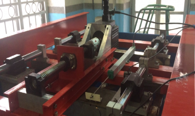
"Wave Generator in the Wave Flume"
Software and Hardware Projects and Facilities
1. Research Projects:
Four research projects on the general topic of physical modeling of breakwaters in a wave flume, conducted in the Hydraulic and Fluid Laboratory, led by Dr. Badii, in collaboration with Dr. Mahmoudov and Engineer Asgari, with consultation from Dr. Naeini.
2. Hardware and Software Facilities:
A. Flumes and Wave Channels:
-
Four metal flumes of various cross-sections, ranging from 3 m to 12 m in length.
-
A 26 m wave channel equipped with an electric wave paddle.
-
A 25 m long, 1 m wide, and 1.3 m high wave flume.
B. Pumps:
-
Three submersible pumps with powers of 0.7 HP and 1 HP.
-
Two centrifugal pumps of 2 HP and 16 HP.
-
An air pump.
C. Tanks:
-
One 1,000 L tank.
-
Two 100 L tanks.
D. Laboratory Equipment:
-
Distilled water generator.
-
High-precision balances (gram and centigram accuracy).
-
Four uniaxial consolidation apparatus.
-
Hot-wire equipment.
-
Educational tools for teaching hydraulic and fluid laboratory experiments, including:
-
Blade tip overflow
-
Two-dimensional water seepage in soil
-
Venturi meter, orifice meter
-
Pipe network flow experiments
-
Buoyancy studies
-
Reynolds number experiments
-
Center of pressure measurement
-
Jet impact experiments
-
Simple Venturi, partial Venturi
-
Sector gate and sluice gate.
-
E. Computers:
-
Three desktop computers for laboratory data acquisition, modeling, and analysis.
Development Outlook
a. Construction of a flume with a moving bed, along with motor, cables, and other components
b. Construction of a tidal basin in the laboratory
c. Research projects on converting wave energy into electrical energy
d. Design of offshore and coastal projects
e. Complete transfer of hydraulic equipment and measurement devices to the Hydraulic Laboratory, particularly ADV, PIV, wind tunnel, and flow velocity measurement systems in channels
f. Purchase of observation equipment for the wind tunnel
g. Equipping the tilting flume with a flow diversion system to a side channel for conducting PhD theses related to piano-key weirs
h. Promotion to encourage all professors, especially domestic faculty members, to utilize the facilities of the Hydraulic and Fluid Laboratory
Team Members
-
Dr. Naeini – Head of the Laboratory and Hydraulic Laboratory course instructor
-
Dr. Badiyi – Research on breakwater modeling experiments
-
Dr. Montazeri – Master’s project supervisor
-
Dr. Ghiyasi – Hydraulic Laboratory course instructor
-
Dr. Naseri – Hydraulic Laboratory course instructor
-
Dr. Akbari – Educational collaborator in the Hydraulic and Fluid Laboratory
-
Eng. Raouf Sobhani – Master’s graduate in Marine Structures
-
Eng. Farhad Hasani – Master’s graduate in Marine Structures
-
Amir Mahdavi – Master’s student
-
Mr. Shariatmadari – Master’s student
-
Ms. Mohammad Hosseini – Master’s student
-
Mr. Nejati – Master’s student
-
Mr. Shahab Baset & Mr. Arash Rafiei – Master’s students
-
Ms. Naseri – Master’s student in Environmental Studies
-
Ms. Rezvan Parvaneh – Master’s student in Water and Hydraulic Structures
-
Mr. Erfan Amini – Master’s student in Marine Structures